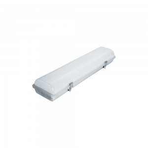
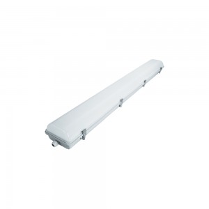
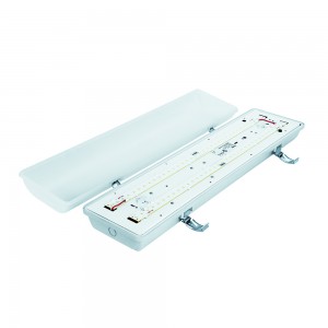
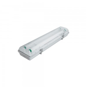
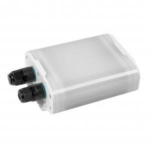
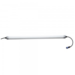
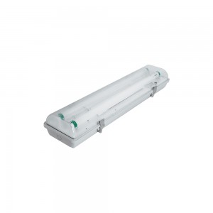
IP65 LED Emergency Light IP 65 LED 2FT 4FT
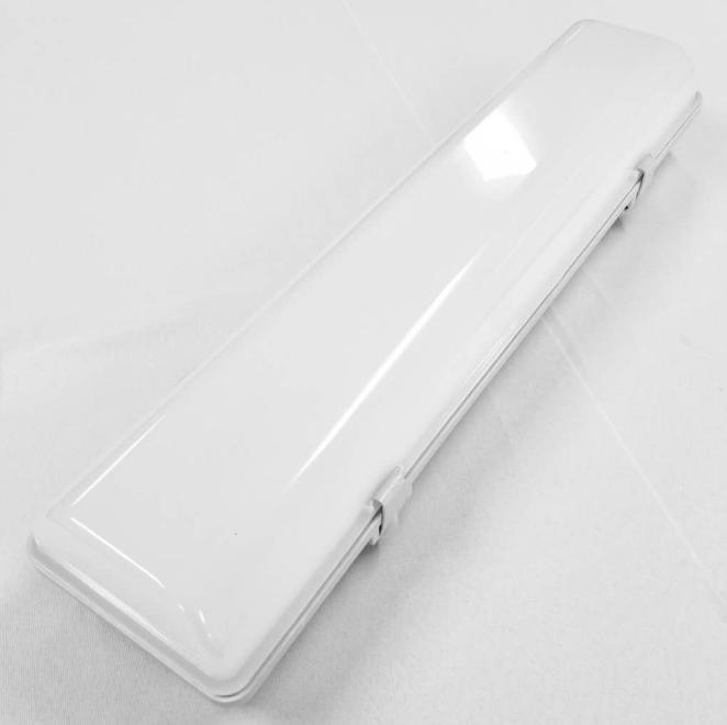
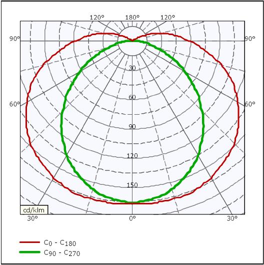
LL02H210 (Standard)
LL02H218 (Standard)
LL02I210 (Emergency)
LL02I218 (Emergency)
LL02J210 (Emergency + Heating System)
LL02J218 (Emergency + Heating System)
Main Features
Housing made of reinforced polyester glass fiber (GRP)
High transparent and impact resistant PC diffuser
Both standard and emergency modes available
Automatic heating system for operations in extremely cold temperature down to -40°C
IP65
| Item Spec. | LL02H210 | LL02H218 | LL02I210 | LL02I218 | LL02J210 | LL02J218 |
| Code | LL02H210-6 | LL02H218-6 | LL02I210-4/6 | LL02I218-4/6 | LL02J210-4/6 | LL02J218-4/6 |
| GE Item No. | 445W2449P001 (120-230V), 445W2449P004 (100V)445W2449P006 (120-230V) | 452W5645P001(1 cable gland)452W5645P002(2 cable glands) | 445W2449P002 (120-230V),445W2449P005 (100V)445W2449P007 (120-230V) | 445W2449P003 (120-230V) 445W2449P008 (120-230V) | 452W5645P003(1 cable gland)452W5645P004(2 cable glands) | |
| Description | Light, LED, Standard SW/CW | Light, LED, Emergency Backup, SW | Light, LED, Emergency Backup, Heating System, CW | |||
| Input Voltage | 120-277V | |||||
| Voltage Range | 100-300V | |||||
| Frequency | 50-60Hz | 50-60Hz | 50-60Hz | 50-60Hz | 50-60Hz | 50-60Hz |
| Rated Input Power | 23W | 45W | 23W | 45W | 23W | 45W |
| 30.5W (Heating System Work) | 52.5W (Heating System Work) | |||||
| Nominal Current | 0.19A | 0.38A | 0.19A | 0.38A | 0.19A | 0.38A |
| 0.26A | 0.44A | |||||
| Operation Temp. | -35~55°C | -35~55°C | -5~55°C | -5~55°C | -35~55°C | -35~55°C |
| Survival Temp. | -40~60°C | -40~60°C | -15~60°C | -15~60°C | -40~60°C | -40~60°C |
| Lamp Type | LED SMD, Cool White | |||||
| Lumen Output | 2100lm | 3700lm | 2100lm | 3700lm | 2100lm | 3700lm |
| Emergency Time | N/A | N/A | > 90Min | > 90Min | > 90Min | > 90Min |
| Battery Lifetime | N/A | N/A | 5 years | 5 years | 5 years | 5 years |
| Meas. Of lighting | L 670mm x W 164mm x H 102mm | L 1275mm x W 161mm x H 102mm | ||||
| Mounting distance | 400±5mm | 984±5mm | ||||
** Code No. LL02H210-X, when X=2: CE approved; X=4: UL approved; X=6: CE+UL approved.
LL02H210/LL02I210/LL02J210:
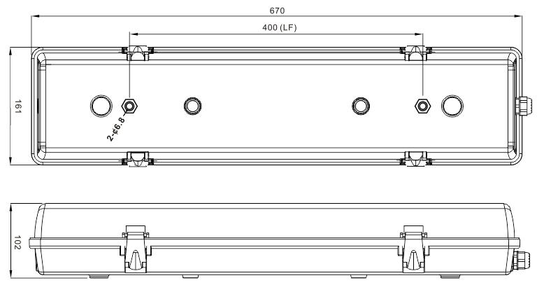
Mounting distance (LF): 400±5mm 2pcs mounting holes ready for M6 bolts.
LL02H218/LL02I218/LL02J218:
Mounting Solution 1

Mounting distance (LF): 984±5mm 2pcs mounting holes ready for M6 bolts.
Mounting Solution 2

Mounting distance (LF): 800±5mm 2pcs mounting holes ready for M6 bolts.
Mounting Illustrations:

| Phenix Part Number | GE Part Number | Number of glands | Gland location | Number of dummy plugs |
| LL02H210/LL02I210/ LL02J210 | 445W2449P001-445W2449PP005 | 2 | On the end adjacent toeach other | 1 |
| LL02H210/LL02I210 /LL02J210 | 445W2449P006-445W2449P008 | 3 | Two on the end adjacentto each otherThird on the opposite endof the other two glands | 0 |
| LL02H218/LL02I218 /LL02J218 | 452W5645P001/452W5645P003 | 1 | On the end near the terminal block | 0 |
| LL02H218/LL02I218 /LL02J218 | 452W5645P002/452W5645P004 | 2 | One on each end | 0 |

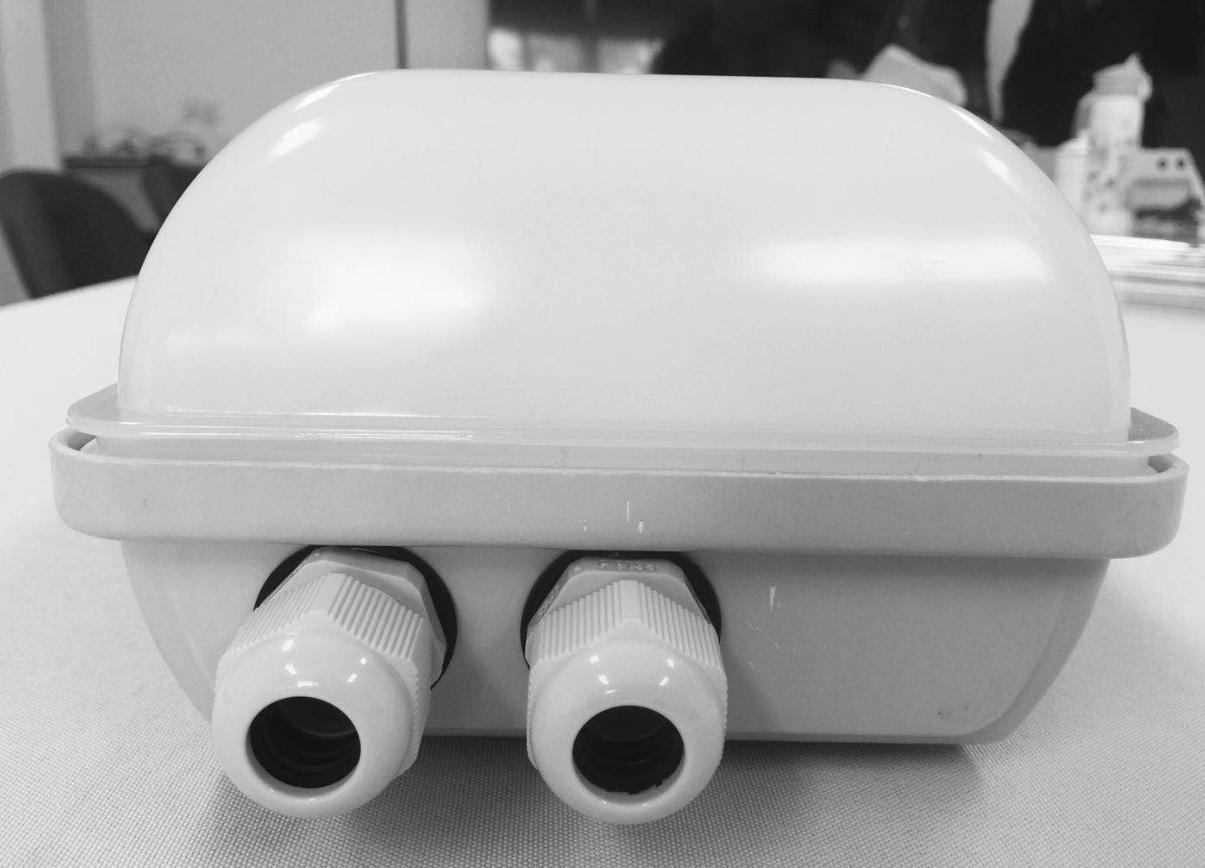
1 (or 2) cable glands on one side
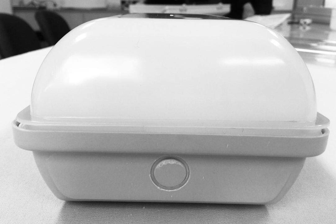
1 or (0) cable gland on the other side
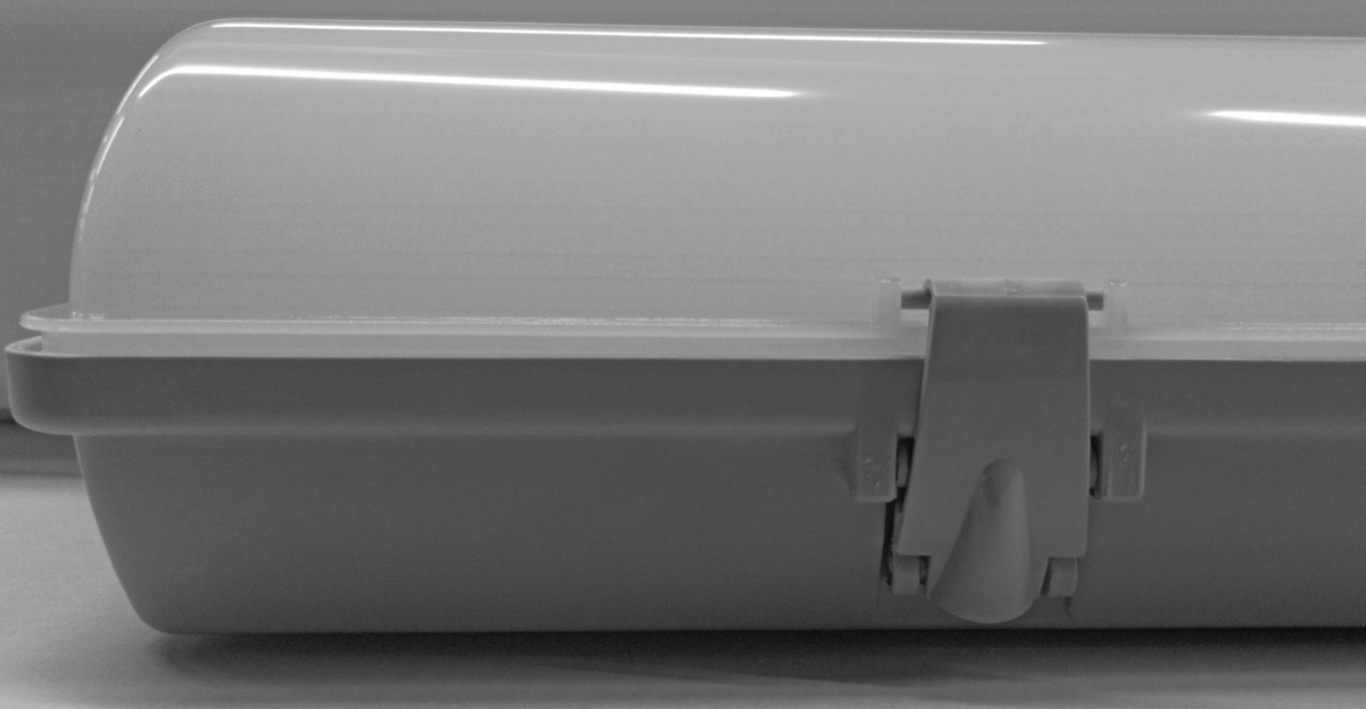
Clips are not falling off
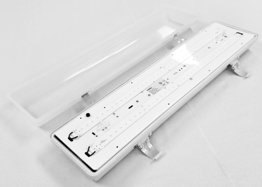
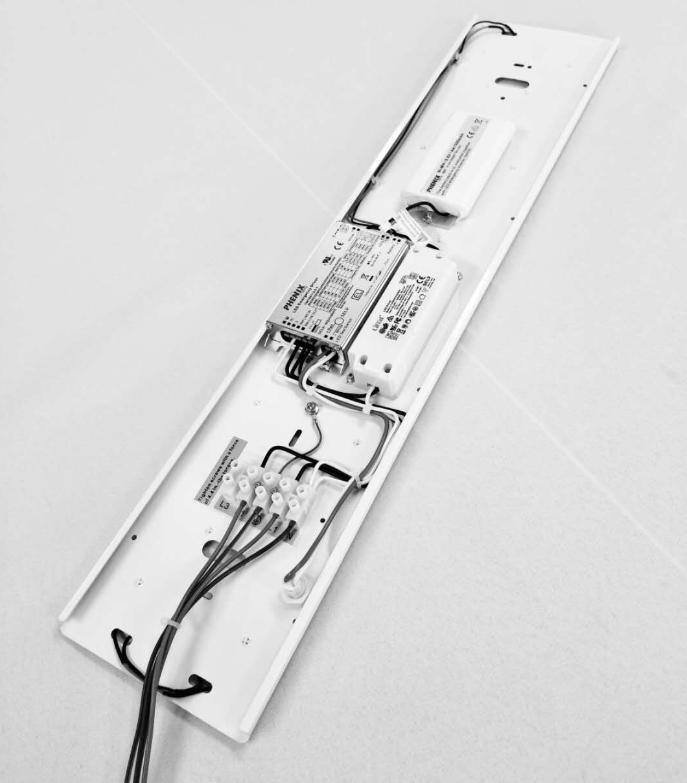

The heating system is used to ensure the luminaire to work well under extremely cold weather down to -40°C.
Input voltage: 120-277V

For emergency (or emergency + heating) luminaires, the following testing and maintenance shall be executed:
Press the LED Test Switch (TSW) to interrupt the power to led emergency driver and to force the luminaire into emergency mode, LED strip lamps are now being lit at a reduced light; the LED signal lamp (LSL) on the TSW turns off in emergency mode. After releasing the TSW, the luminaire returns to normal operation after a momentary delay, LED strip lamps are lit with full power, and the LSL turns on.
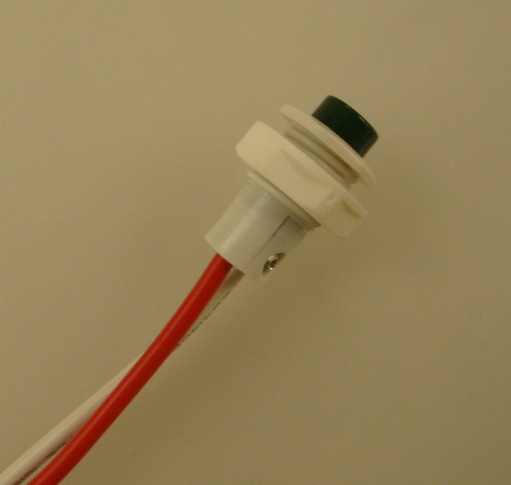
LED Test switch (TSW)
Note: If the end user needs the luminaire to go into the emergency mode only when the mains power is failed, an external switch should be added on the input terminal.
After installing the external switch, the luminaire need to be tested (both on and off status) if it complies the below situations:
When the mains power is on:
Turn on the external switch, the luminaire is in normal mode: All LED strip lamps are lit, and the LSL is lit, and the battery is being charged.
Turn off the external switch, the luminaire is in normal mode: all LED strip lamps are off, the LSL is lit, and the battery is being charged.
When the mains supply is failed:
No matter if the external switch is turned on or off, the luminaire goes into the emergency mode. All LED strip lamps are lit at a reduced output. The LSL is off and the battery is being discharged.
1.Instant Auto Test
When the system is connected well and powered on, the luminaire will auto test if the load and battery pack are connected well and if the battery is being charged normally. If there is any abnormal situation, the LED Signal Lamp (LSL) is flickering. When the abnormity is removed, the LSL indicates normally.
2.Preprogrammed scheduled Auto Test
– Carry out first monthly Auto Test after Initial power on for 24 hours to 7 days, afterwards, carry out a monthly Auto Test every 30 days.
– Carry out an annual Auto Test every 52 weeks after first powered on.
– Auto Test timing
To reduce the conflict that Auto Test is executed when the lighting is in use, the preprogrammed scheduled Auto Test will be executed 2 hours later than the normal operation is disconnected (switched off). For applications where lightings remain illuminated, the module will postpone the scheduled test accordingly, but should not later than the preprogrammed scheduled latest test time.
– Monthly Auto Test
Monthly Auto Test should be executed every 30 days and to test:
If the switchover of normal and emergency mode is normal;
If the emergency function and battery’s charging and discharging condition is normal;
Auto Test time is about 30 seconds.
– Annual Auto Test
Annual Auto Test should be executed after 24 hours full charging and to test:
If the battery’s voltage is equal or higher than the limit after 24 hours full charging;
If the emergency operation time is over 90 minutes;
If the battery voltage after 90 minutes emergency operation is still equal or high than 87.5% of the battery voltage before testing.
– During the Auto Test, in case a power failure happens and the power cannot be on till the Auto Test completes, then the Auto Test will be executed again 24 hours later after the power is on.
– If the emergency mode makes the battery discharged completely under the power off condition, then the preprogrammed scheduled Auto Test will resume the first time when the power is connected.
3.Manual Test
– Press LED test switch (LTS) one time, then go into emergency mode and back to normal mode rapidly.
– Press LTS 2 times continuously within 5 seconds, then go into monthly test. After finish, the next monthly test will count from this date.
– Press LTS 3 times continuously within 5 seconds, then go into annual test. After finish, the next annual test will count from this date.
– During the manual test, press LTS 3 times within 5 seconds, then the manual test can be terminated. (The preprogrammed scheduled Auto Test time will not change)
4.LED Signal Lamp (LSL) indication
– LSL on: Normal
– LSL off: Power failure
– LSL gradual change: In testing
– LSL flickering: Abnormal
| No. | Item No | Outer Carton L(CM) | Outer CartonW(CM) | Outer CartonH(CM) | Qty/CTN (PCS) | N.W/CTN (KGS) | G.W/CTN (KGS) | |
| 1 | LL02H210 | 70 | 37 | 25.5 | 4 | 16.5 | 18.2 | |
| 2 | LL02H218 | 130.5 | 37 | 25.5 | 4 | 19.8 | 21.3 | |
| 3 | LL02I210 | 70 | 37 | 25.5 | 4 | 17.7 | 19.4 | |
| 4 | LL02I218 | 130.5 | 37 | 25.5 | 4 | 20.8 | 22.3 | |
| 5 | LL02J210 | 70 | 37 | 25.5 | 4 | 18.5 | 20.4 | |
| 6 | LL02J218 | 130.5 | 37 | 25.5 | 4 | 21.5 | 22.8 | |
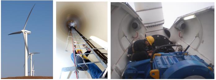
Wind power system
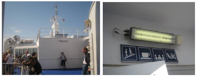
Ships
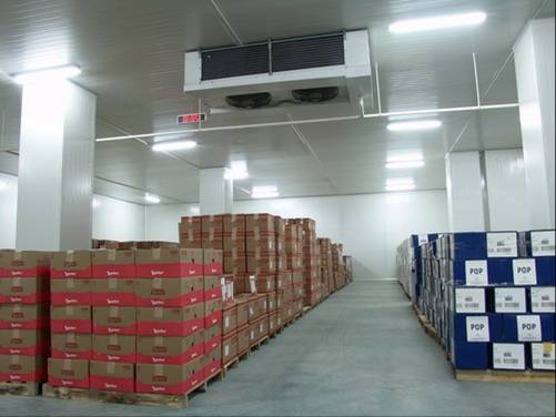
Freezers
Any other harsh indoor and outdoor locations
